 |
pinocchio
2.6.17
A fast and flexible implementation of Rigid Body Dynamics algorithms and their analytical derivatives
|


|
|
pinocchio
2.6.17
A fast and flexible implementation of Rigid Body Dynamics algorithms and their analytical derivatives
|
|
Joints are not simple objects, it can be difficult to deal with. To facilitate their description Pinocchio use the lie algebra which is describe in the *Dealing with Lie bgroup geometry * chapter. Let's take the base joints and express them using lie algebra :
the revolute joint is a \( SO(2)\) object.
\( Mat_{move} = \begin{bmatrix} 0\\0\\1\\0\\0\\0 \end{bmatrix} \ \ Mat_{cons} = \begin{bmatrix} 1 &0 &0 &0 &0 \\ 0 &1 &0 &0 &0 \\0 &0 &0 &0 &0 \\0 &0 &1 &0 &0 \\ 0 &0 &0 &1 &0 \\0 &0 &0 &0 &1 \end{bmatrix} \)
the cylindrical joint :
\(Mat_{move} = \begin{bmatrix} 0 &0 \\ 0 &0 \\ 1 &0 \\ 0 &0 \\ 0 &0 \\ 0 &1 \end{bmatrix} \ \ Mat_{const} = \begin{bmatrix} 1 &0 &0 &0 \\ 0 &1 &0 &0 \\ 0 &0 &1 &0 \\ 0 &0 &0 &1 \\ 0 &0 &0 &0 \end{bmatrix} \)
The spherical joint is a \( SO(3) \) object.
\( Mat_{move} = \begin{bmatrix} 1 &0 &0\\0 &1 &0\\0 &0 &1\\0 &0 &0\\0 &0 &0\\0 &0 &0 \end{bmatrix} \ \ Mat_{cons} = \begin{bmatrix} 0 &0 &0 \\ 0 &0 &0 \\0 &0 &0 \\1 &0 &0 \\ 0 &1 &0 \\0 &0 &1 \end{bmatrix} \)
The planar joint is a \( SE(2) \) object.
\( Mat_{move} = \begin{bmatrix} 0 &0 &0\\0 &0 &0\\0 &0 &0\\1 &0 &0\\0 &1 &0\\0 &0 &1 \end{bmatrix} \ \ Mat_{cons} = \begin{bmatrix} 1 &0 &0 \\ 0 &1 &0 \\0 &0 &1 \\0 &0 &0 \\ 0 &0 &0 \\0 &0 &0 \end{bmatrix} \)
The free floating joint is a \( SE (3) \) object. The movement and constraints matrices are 6 by 6 matrices.
\( Mat_{move} = \begin{bmatrix} Id \end{bmatrix} \ \ Mat_{const} = \begin{bmatrix} 0 \end{bmatrix} \)
The matrices respectively represent the movements and constraints in a landmark related to the joint itself.
The kinematic chain is the mathematical model that makes it possible to calculate the position of all the elements linked by successive joints of a robot, and in particular the installation of the end elements, from the rotations (and possibly the translations) applied to each joint. The calculation is done step by step, starting from the installation of the initial element. The installation of the final element is mathematically unique and perfectly defined, except for any rounding errors during successive calculations.
In practice, the problem is quite different. We know the installation of the initial element (for example the robot base), and we want to impose the installation of one of its elements, usually the final element, such as for example the installation of the clamp at the end of the robot arm. In the general case, there are several solutions for rotating the joints that give the same final installation. This point can be easily verified by observing that our hand can hold a glass in the same position while we can lift or not our elbow by changing the rotations on the shoulder and wrist.
Inverse kinematics (often abbreviated as IK) refers to all the methods of calculating positions and rotations in order to obtain a desired pose. Since the problem can admit several solutions, optimization techniques must be used. Reverse kinematics methods used in robotics can take into account the technical data of robots, for example by maintaining the position of the robot's center of gravity, or by preventing the robot from tipping over.
Finally, it should be noted that even if there is only one way to obtain the final installation, the rotations can be done in a different order, and the trajectory of the final element will be different in each case.
In the case represented by the picture below, there are a large number of possibilities, the arm could have made a curved or linear trajectory, the rotation could have been made before or after the translations etc.
TODO : Pyrene's moving picture
Joints are essentials components of a robot to allow it to move in his environment. Joints are in some ways robot's articulations. There are several types of them, each caracterised by its shape and degrees of freedom:
Furthermore, we can creat more complicated joints called composite joints by combining them with each other.
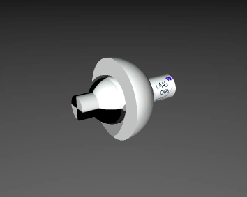
The most simple rotational joint we have to deal with is the revolute joint, he has juste one degree of freedom so it is possible just to focus on it. We can find three differents types of revolute joints, each type can rotate around one of the 3-axis, x-axis, y-axis or z-axis. Revolute joints are used to describe rotational movements.
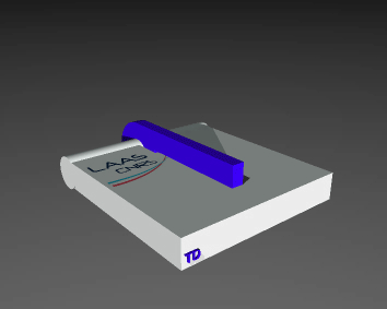
Again a one degree of freedom joint but this time no more rotations. With a Prismatic joint we are able to describe translational movements. As the revolute joint, we can set up three differents Prismatic joints, each following one axis which are the x-axis, y-axis or z-axis.
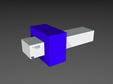
The cylindrical joint has two degrees of freedom, one of rotation and this other of translation.
The spherical joint is the closest thing to an human's articulation, it is very close for our hip for example but even our body is restricted, we can not do a full tour around one of the 3-axis. This joint is almost the same except for the fact it can do a full rotation on itself. So this joint can moved around the 3-axis. He allows the robot to move its members as we do and even better.
As its name suggests, a planar joint allows movements that a object can do in a plan. Indeed, he allows two translations and one rotation, therefore it has three degrees of freedom. We find this type of movement all over our daily lives, a car has this movement, we have it most of the time when we walk on a flat floor and for example this is exactly Tiago's movement.
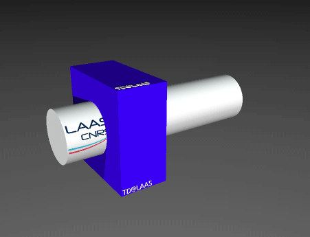
This one is the complementary of spherical joint, it gives the possibility to move in 3-dimensional space but only by translations. This is a three degrees of freedom joint. To link this to our body we have to imagine that we block our ankle's articulation to prevent rotations and then we move our foot by raising and lowering it, going up and down, to the sides and front and back. This is precisely what a translation joint allows.
This joint allows a free movement in the 3-dimensional space with its six degrees of freedom. This is also the harder non-composite joint to manage because of the possibilities it creates.
 1.8.17